Daewoo DWP-28W2ZZF Service Manual
Browse online or download Service Manual for CRT TVs Daewoo DWP-28W2ZZF. Daewoo DWP-28W2ZZF Service manual User Manual
- Page / 70
- Table of contents
- BOOKMARKS
- Service Manual 1
- TABLE OF CONTENTS 2
- Service manual WP-795 10
- SCHEMATIC DIAGRAM 15
- EXPLODED VIEW 16
- PRINTED CIRCUIT BOARD 17
- ELECTRICAL PARTS LIST 18
- DAEWOO ELECTRONICS CO., LTD 27
- - 4 31
- - 8 35
- Block diagram TDA8944J 41
- O(guard) 42
- Block diagram TDA6107Q 45
- Chassis block diagram : IF 53
- Sound signal flow diagram 57
Summary of Contents
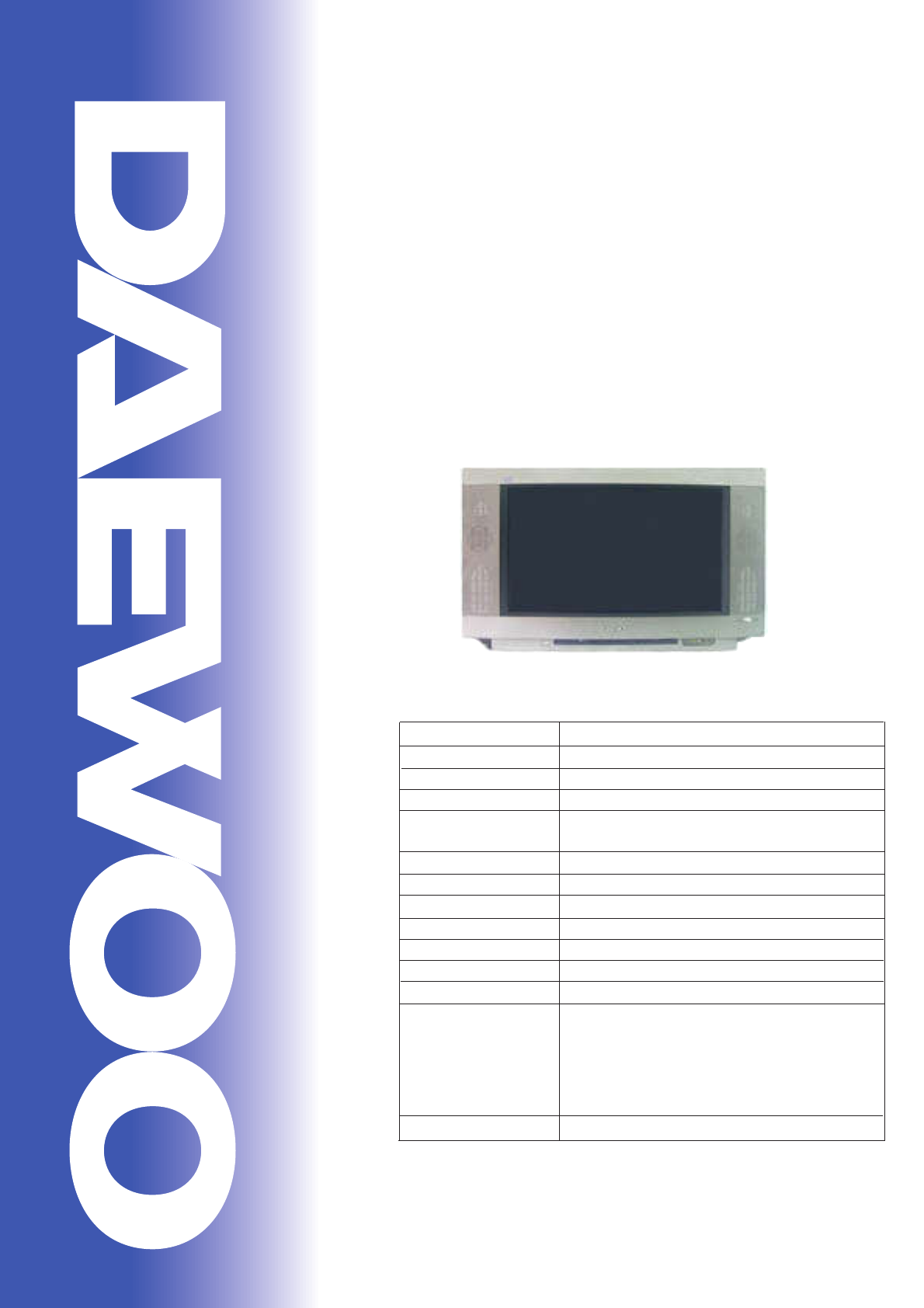
Service ManualColor Television 66cm Wide StereoCHASSIS : WP-795Model : DWP-28W2ZZF DWP-28W2ZLF Dec. 2000 DAEWOO ELE
Service manual WP-795 - 9 - 2 - Safety instruction WARNING: Only competent service personnel may carry out work involving the testing or repair of th
Service manual WP-795 - 10 - 3 - Circuit Block diagram
Service manual WP-795 - 11 - 4 - Alignment instructions 4-1 Microcontroller configuration : Service mode To switch the TV set into service mode pleas
Service manual WP-795 - 12 - 4-3-4 - Vertical geometry - Adjust the Vertical Amplitude, Shift, S-Correction and Slope to compensate for vertical dist
Service manual WP-795 - 13 - EW Trapez 4-3-7 - AGC - Adjust the antenna signal level at 68 dBµV± 2 - Set RF AGC to 0. - Increase RF AGC level and s
- 14 -SCHEMATIC DIAGRAM
- 15 -EXPLODED VIEW1. DWP-28W2ZZF/28W2ZLF
- 16 -PRINTED CIRCUIT BOARDPCB MAIN
- 17 -ELECTRICAL PARTS LISTLOC PART CODE PART NAME PART DESCRIPTION REMARKZZ100 48B3740A13 TRANSMITTER REMOCON R-40A13 (AAA) 2ZZ110 PTACPWD395 ACCESSO
- 18 -C801 CL1JB3474K C LINE ACROSS AC250V 0.47MF U/C/SNDF/SV IC805 CEYN2G181P C ELECTRO 400V LHS 180MF (25X35)C812 CH1AFE472M C CERA AC 4KV 4700PF M
1TABLE OF CONTENTS APPENDIX (Appendix is provide only by internet [http://svc.dwe.co.kr])MAIN FEATURES...
- 19 -C662 CMXM2A224J C MYLAR 100V 0.22MF JC668 CMXM2A224J C MYLAR 100V 0.22MF JC669 CMXM2A224J C MYLAR 100V 0.22MF JC810 CBXB3D102K C CERA SEMI 2KV B
- 20 -C412 CEXF2C339V C ELECTRO 160V RSS 3.3MF (8X16) TPC414 CMXM2A104J C MYLAR 100V 0.1MF J (TP)C418 CCXB1H102K C CERA 50V B 1000PF K (TAPPING)C420 C
- 21 -Q505 TKTC3198Y- TR KTC3198YQ508 TKTC3198Y- TR KTC3198YQ510 TKTA1266Y- TR KTA1266Y (TP)Q511 TKTA1266Y- TR KTA1266Y (TP)Q512 TKTC3198Y- TR KTC3198
- 22 -D831 D1N4937G-- DIODE 1N4937G (TAPPING)D840 D1N4148--- DIODE 1N4148 (TAPPING)D841 D1N4148--- DIODE 1N4148 (TAPPING)D904 D1N4937G-- DIODE 1N4937G
- 23 -J073 85801065GY WIRE COPPER AWG22 1/0.65 TIN COATINGJ074 85801065GY WIRE COPPER AWG22 1/0.65 TIN COATINGJ075 85801065GY WIRE COPPER AWG22 1/0.65
- 24 -R539 RD-AZ101J- R CARBON FILM 1/6 100 OHM JR540 RD-AZ101J- R CARBON FILM 1/6 100 OHM JR541 RD-AZ101J- R CARBON FILM 1/6 100 OHM JR543 RD-AZ472J-
- 25 -RA40 RD-AZ102J- R CARBON FILM 1/6 1K OHM JRA41 RD-AZ102J- R CARBON FILM 1/6 1K OHM JRA44 RD-AZ682J- R CARBON FILM 1/6 6.8K OHM JRA45 RD-AZ101J-
DAEWOO ELECTRONICS CO., LTD686, AHYEON-DONG MAPO-GUSEOUL, KOREAC.P.O. BOX 8003 SEOUL, KOREATELEX : DWELEC K28177-8CABLE : "DAEWOOELEC"E-mail
Appendix Service manual WP-795 - 1 - 1 - IC desc
Appendix Service manual WP-795 - 2 - Data Capture
Service manual WP-795 - 2 - 1 - Main features 1-1 Specifications TV standard PAL - SECAM B/G D/K, PAL I/I, SECAM L/L’ Sound system NICAM B/G, I, D/K
Appendix Service manual WP-795 - 3 - Data Captu
Appendix Service manual WP-795 - 4 -
Appendix Service manual WP-795 - 5 - TV processor
Appendix Service manual WP-795 - 6 - RF AGC in 6
Appendix Service manual WP-795 - 7 - B0 53 BLUE
Appendix Service manual WP-795 - 8 -
Appendix Service manual WP-795 - 9 - 1-2 MSP3415D
Appendix Service manual WP-795 - 10 - - simple co
Appendix Service manual WP-795 - 11 - TV standards TV sy
Appendix Service manual WP-795 - 12 - 11 TP In /
Service manual WP-795 - 3 - 20 Video Input 1 Vpp ± 3dB, Impedance 75Ω 21 Common Earth 21 Pin EURO-SCART 2 : Pin Signal Description Matching val
Appendix Service manual WP-795 - 13 - 59 ANA_IN1-
Appendix Service manual WP-795 - 14 - Block diagram TDA8
Appendix Service manual WP-795 - 15 - Pinning Pin Symbol
Appendix Service manual WP-795 - 16 - 1-4-1 TDA8358J An E
Appendix Service manual WP-795 - 17 - 1-5 TDA6107Q The TDA
Appendix Service manual WP-795 - 18 - Block diagram TDA
Appendix Service manual WP-795 - 19 - 1-7 STR - F6653 1-
Appendix Service manual WP-795 - 20 - 1-7 -4 pin d
Appendix Service manual WP-795 - 21 - 2 - Circuit
Appendix Service manual WP-795 - 22 - FUNCTIONAL
Service manual WP-795 - 4 - 1-2 Channel table FREQUENCY TABLE CH EUROPE CCIR FRANCE GB(IRELAND) EAST OIRT C01 46.25 - 45.75 49.75 C02 48.25 55.
Appendix Service manual WP-795 - 23 - In the type
Appendix Service manual WP-795 - 24 - The SECAM de
Appendix Service manual WP-795 - 25 - 2-2 IF The
Appendix Service manual WP-795 - 26 - Chassis b
Appendix Service manual WP-795 - 27 - 2-3 Source s
Appendix Service manual WP-795 - 28 - Push-Pull Th
Appendix Service manual WP-795 - 29 - Phase and A
Appendix Service manual WP-795 - 30 - Sound sign
Appendix Service manual WP-795 - 31 - 2-6 Sound am
Appendix Service manual WP-795 - 32 - The guard s
Service manual WP-795 - 5 - C46 671.25 671.25 671.25 671.25 C47 679.25 679.25 679.25 679.25 C48 687.25 687.25 687.25 687.25 C49 695.25 695.25 695.2
Appendix Service manual WP-795 - 33 - 2-8 Power su
Appendix Service manual WP-795 - 34 - When the po
Appendix Service manual WP-795 - 35 - 2-8 -2-1 S
Appendix Service manual WP-795 - 36 - C When the M
Appendix Service manual WP-795 - 37 - 2-9 TV start
Appendix Service manual WP-795 - 38 - . If the TV
Appendix Service manual WP-795 - 39 - - When the
Appendix Service manual WP-795 - 40 - On normal r
Appendix Service manual WP-795 - 41 - 2-9-2-1-3 p
Appendix Service manual WP-795 - 42 - 2-9-2-2 TV
Service manual WP-795 - 6 - S18 280.25 136.00 295.25 280.25 S19 287.25 160.00 303.25 287.25 S20 294.25 - - 294.25 S21 303.25 303.25 - 303.25 S22
Appendix Service manual WP-795 - 43 - 2-9-2-2-2
Service manual WP-795 - 7 - 1-3 ATSS sorting method The TV set sweeps all the TV bands from beginning of VHF to end of UHF. The TV controlling softwa
Service manual WP-795 - 8 - Special case : France If France is selected the TV controlling software sweeps the whole TV bands firstly with France syst
Related products and manuals for CRT TVs Daewoo DWP-28W2ZZF
 (43 pages)
(19 pages)
(50 pages)
(49 pages)
(43 pages)
(50 pages)
(60 pages)
(80 pages)
(59 pages)
(35 pages)
(53 pages)
(89 pages)
(58 pages)
(86 pages)
(142 pages)
(102 pages)
(77 pages)
(43 pages)
(19 pages)
(50 pages)
(49 pages)
(43 pages)
(50 pages)
(60 pages)
(80 pages)
(59 pages)
(35 pages)
(53 pages)
(89 pages)
(58 pages)
(86 pages)
(142 pages)
(102 pages)
(77 pages)
© 2020, manymanuals.com. All rights reserved. | 1.070 s |
 Manymanuals.com
 Manymanuals.de
 Manymanuals.fr
 Manymanuals.it
 Manymanuals.pl
 Manymanuals.cz
 Manymanuals.es
 Manymanuals-pt.com
Comments to this Manuals